83 Jean St, Grange QLD 4051
Mon-Fri 07:30 AM - 04:00 PM - Sat - 8:00 - 12 - Sunday Closed

A hallway light in a Brisbane home has started playing up. The switch clicks, the toggle feels loose, but the lamp stays dark. Before removing the plate, the sensible question isn't just how to wire a switch. It's whether the switch is the fault at all, whether the circuit is protected, and whether the work falls within what a homeowner can legally do.
Switch electrical wiring sits inside a regulated fixed installation. AS/NZS 3000:2018 sets the minimum safety requirements for those installations, while its deemed-to-comply methods cover practical design, construction and testing requirements. In Australia, the standard took effect in most states and territories on 1 January 2019, as outlined by Standards Australia's AS/NZS 3000:2018 publication.
The guide below explains the common switch arrangements, the limits of sensible DIY work, and the Queensland compliance issues that often turn a simple replacement into a switchboard or circuit upgrade.
The switch may be the culprit. A cracked toggle, worn internal contact or terminal discoloured by heat can make a fitting unreliable, especially in an older home. A loose faceplate is usually a mechanical nuisance, but scorching, a burning smell, crackling or a warm mechanism points to a fault that shouldn't be treated as a cosmetic replacement.
The symptom may also be coming from somewhere else. A tripped RCD can remove power from the lighting or socket circuit, a failed lamp can make a healthy switch look defective, and a loose connection at the switchboard can affect more than one fitting. If an entire room is dead, lights flicker across separate points, or the safety switch trips, the switch is only the visible end of the problem.
A like-for-like replacement is the only category that belongs in a cautious DIY conversation. That means an existing single-pole mechanism replaced with an identical compatible mechanism, an existing two-point switch replaced with the same terminal arrangement, a compatible dimmer installed according to its manufacturer's instructions, or a loose faceplate tightened without disturbing conductors.
Even those jobs require proper isolation and testing. Product markings, terminal layouts and existing cable arrangements vary between Clipsal, HPM and other mechanisms, so a photograph is useful for identification, not a substitute for proving the circuit is dead.
Practical rule: If the fault affects more than one fitting, stop treating it as a switch replacement.
New circuits, switchboard alterations and work in wet areas are off-limits for an unlicensed homeowner. Stop immediately if removing a plate exposes asbestos-backed board, brittle rubber-sheathed cable, heat-damaged insulation or unfamiliar conductors. Don't cut, pull or disturb those materials.
Queensland's safety-switch programme shows why this caution matters. Government reporting recorded approximately 400 serious electrical incidents and 44 electrocution fatalities over the 10 years from 2001–2002 to 2011–2012, according to the Queensland Electrical Safety Office review. The switch is a control in a larger system, not an isolated plastic accessory.
Preparation should look the same whether you're checking a loose plate or assessing a replacement mechanism. Identify the circuit at the switchboard first. Queensland homes often have unclear or outdated labels, so don't rely on a handwritten description that says “lights” if you haven't verified it.
Turn the suspected breaker off, then test the actual fitting. Operate the switch and confirm the light is no longer energised. If other points remain live, you may have isolated the wrong circuit or discovered a shared arrangement that needs professional assessment.
Identify the exact breaker. Switch breakers off one at a time while checking the fitting. Never assume the nearest label is correct.
Isolate and prevent re-energisation. Lock the breaker off where possible, or clearly tag and tape it so another person can't restore power while the plate is removed.
Prove the circuit dead. Use a properly functioning two-probe tester or multimeter at the switch terminals. Check active to earth, active to neutral and across the switch in both positions. A single-probe non-contact tester can help indicate voltage, but it isn't enough on its own to prove a circuit safe.
Prepare the work area. Use insulated tools, safety glasses and a clear working space. Keep loose metal objects away from the mechanism and don't work in damp conditions.
Check the protection and legal position. New domestic final sub-circuits require RCD protection under AS/NZS 3000:2018. Queensland also places a safety-switch obligation on residential owners after ownership changes and when a residential tenancy begins. The regulator explains that an approved safety switch for a general-purpose socket outlet must be installed within 90 days after becoming the owner, and again within 90 days after starting a residential tenancy agreement, in the Queensland electrical safety regulation guidance.
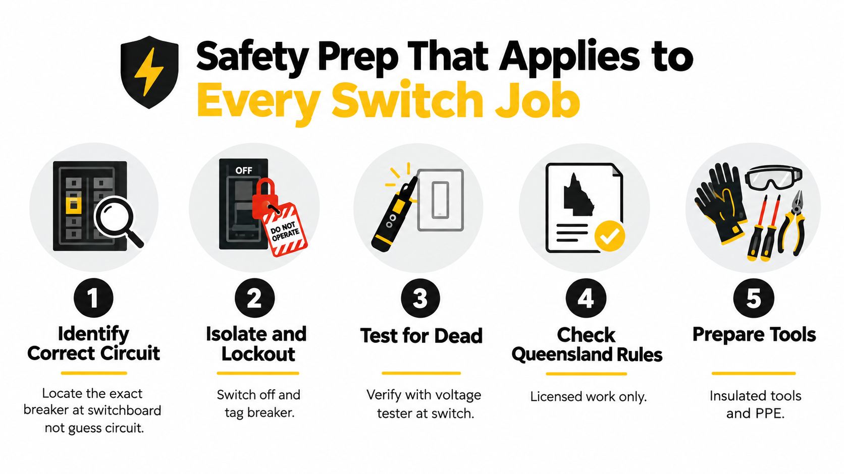
A switch replacement doesn't become safe because it's quick. The separation between a controlled job and a dangerous one is usually isolation, identification and testing. For a practical Australian walkthrough, keep the DLG guide to wiring a switch safely alongside the manufacturer's instructions, but use a licensed electrician when the existing wiring doesn't match the expected arrangement.
A single-pole switch controls one light from one location. The useful mental model is that the switch interrupts the active conductor, not the neutral. At the mechanism, you may encounter an incoming active, a switched active to the load, a neutral joined through the box and an earth conductor connected to the protective earthing arrangement.
Typical modern colour identification uses red or brown for active, black or blue for neutral, and green/yellow for earth. Colour alone isn't proof, particularly in older Queensland homes or installations that have been altered over the years.
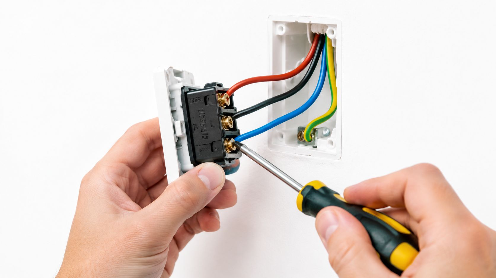
The incoming active is energised upstream of the switch. It enters the common or line terminal. The load, or switched active, leaves the mechanism and carries power to the light only when the switch is closed.
The neutral normally joins through the back box or cable route and doesn't get broken by a standard switch. The earth conductor connects to the protective earth terminal, the metal box where applicable, and the mechanism's earth link according to the fitting design.
Before disconnecting anything, photograph the arrangement and label each conductor. A photograph can preserve the original layout, but it can't correct an installation that was already wrong.
In a loop-at-switch arrangement, the supply enters the switch location, which can make the active and switched active easy to identify at the mechanism. In a loop-at-light arrangement, the supply first reaches the light fitting and the switch cable forms the control path. The conductors at the wall can therefore look different from what a first-time installer expects.
For new work, the presence of a neutral at the switch is an important design consideration under AS/NZS 3000:2018. An older switch location may not contain the neutral needed for a smart switch or electronic device. Adding one often means installing new cable through the wall or roof space, which is a sensible point to stop.
If a like-for-like replacement is appropriate, transfer one identified conductor at a time to the corresponding terminal on the compatible mechanism. Tighten terminals to the manufacturer's specified torque, keep copper fully enclosed, refit the plate without crushing cables, then restore power and test operation. The Australian switch wiring diagram guide from DLG Electrical provides a visual reference for the common and switched-active arrangement.
Australian electricians often call this a two-way or two-point switching arrangement. It differs from a single-pole circuit because two mechanisms control the same lamp. Each switch has a common terminal and traveller terminals, sometimes marked with numbers or a distinct terminal colour.
The active supply connects to the common of the first switch. Two traveller conductors run between the traveller terminals of both switches. The common of the second switch sends the selected path onward as the load, or switched active, to the lamp.
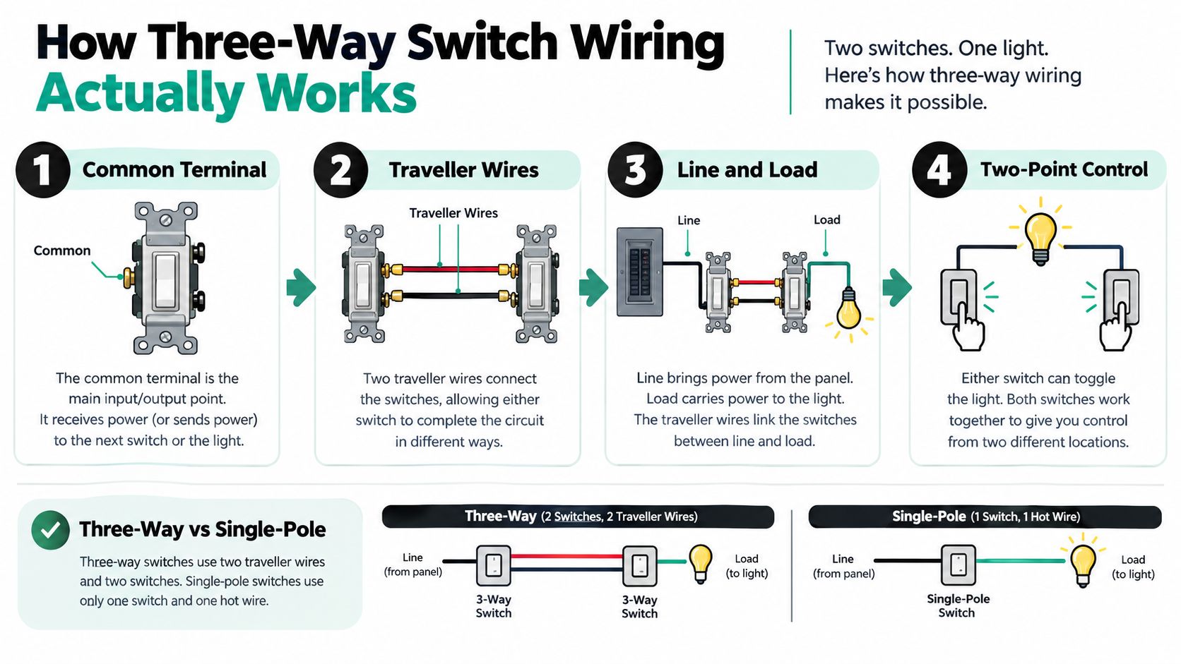
Each switch selects one of two traveller paths. When both switches select a continuous path, the active reaches the lamp and it illuminates. Flipping either switch changes the selected path, so the light changes state from either end of the hallway, stairwell or room.
The cable between the switch points is commonly 3-core plus earth. That arrangement provides the conductors needed for the common and the two travellers, with the protective earth maintained separately. The exact cable and termination arrangement must still be checked at the installation, rather than assumed from the number of visible wires.
The most frequent mistake during a like-for-like swap is moving a conductor from common to a traveller terminal because the old mechanism's markings weren't recorded. A switch can physically fit the wall plate and still operate incorrectly if the common conductor is misplaced.
Electronic or smart three-way mechanisms may use a different logic and may require a neutral at the switch. They can also require a matching companion device rather than two ordinary mechanisms. Manufacturer diagrams take priority over a generic pattern, especially where the load includes LED drivers or another electronic control.
A two-point circuit is easy to describe and easy to misidentify. Terminal markings matter more than wire position.
If the existing mechanism has unusual links, extra cables, mixed colours or signs of previous alterations, don't experiment. An electrician can trace the common, travellers and load, then test the circuit instead of relying on assumptions made from the faceplate.
A dimmer is not just a switch with a brightness knob. Its internal electronics must match the load, the lamps and the switching arrangement. The wrong combination can produce flicker, buzzing, poor low-level performance or nuisance tripping.
| Dimmer type | Best for | LED compatibility | Watch out for |
|---|---|---|---|
| Leading-edge | Older incandescent lamps and suitable low-voltage halogen with magnetic transformers | Often poor with modern LED lamps | Buzzing, minimum-load issues and transformer compatibility |
| Trailing-edge | LED lamps and electronic low-voltage loads | Usually the more suitable modern option | The lamp and driver must still be approved for dimming |
| Smart or electronic | App control, voice control and scheduling | Depends on the device and compatible lamps | Often needs a neutral, correct load limits and a suitable companion mechanism |
Leading-edge dimmers can work with older resistive lamps and magnetic transformers, but many LED lamps don't respond cleanly to that waveform. Trailing-edge units are generally better suited to LED and electronic-low-voltage loads, although “LED compatible” on the box doesn't remove the need to check the lamp and dimmer combination.
Smart dimmers add convenience, but the back box must contain the conductors the device requires. A missing neutral is common in older switch locations, and installing one may involve cable replacement rather than a simple mechanism swap.
Isolate at the switchboard and prove the circuit dead. Identify the active, switched load and earth, then follow the dimmer's diagram for the common or line and load terminals. Don't use a generic switch diagram for a device with electronics unless the manufacturer expressly shows that arrangement.
Check the dimmer's VA rating against the connected load. Multi-gang plates can require derating, so the capacity may reduce when several dimmers sit together. Two-point switching also needs care. A conventional dimmer won't automatically work in a standard two-way circuit, and some arrangements require a specific dimmer and remote or retrofit module combination.
A dimmer that runs hot, buzzes or flickers is giving you a compatibility warning. Turn it off at the breaker and have the load, wiring and device checked rather than repeatedly cycling it.
The switch is often where the homeowner notices the fault, not where the fault begins. A buzzing mechanism may reflect an incompatible dimmer, a loose termination or a circuit problem. A dark light may be a failed lamp, an open neutral or an upstream protective device.
Ageing switchboards deserve particular attention. Older homes may not have complete RCD coverage, may contain mixed-era cable types, or may have altered wiring that no longer resembles the original installation. Aluminium tails in some older homes, damaged insulation and an uncertain MEN arrangement require professional inspection, not a new decorative plate.
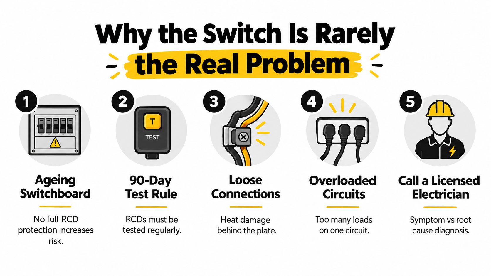
Queensland's safety-switch requirements have expanded over time. Government documents estimated that about 500,000 Queensland homes did not have a safety switch, while another assessment identified about 500,000 pre-1992 domestic dwellings without one, as recorded in the Queensland Ombudsman workplace electrocution report.
That history matters when a landlord, renovator or buyer touches an older installation. The 90-day ownership and tenancy requirement can make the surrounding switchboard condition more important than the replacement mechanism itself. A property sale, a new tenancy or a renovation can be the point at which an owner discovers that safety-switch coverage, circuit separation and documentation need attention.
Adding a circuit, altering a switchboard, extending wiring or working in a wet area goes beyond a switch plate. So does any job involving unsafe cable, damaged enclosures, inadequate earthing or a circuit that fails testing. AS/NZS 3000:2018 requires design, construction and verification against minimum installation rules, not merely a switch that appears to operate.
The current Wiring Rules include Amendment 3 published in 2025, and Queensland's Electrical Safety Regulation 2026 is in force, according to Australian wiring-rule guidance from CCC Engineering. Recent Australian guidance points towards broader safety-switch coverage across final sub-circuits, including equipment such as air conditioning and hot water systems. That's why a small switch job can uncover a larger compliance decision.
Start with the symptom, then identify the likely cause, then choose the safest first check. Don't remove a mechanism because the lamp is dark until you've checked the lamp, the RCD and the circuit condition.
| Symptom | Likely cause | First check |
|---|---|---|
| Light stays off with the switch on | Open connection at the switch, failed lamp or broken neutral at the light | Check the lamp and switchboard protection. If wiring inspection is needed, isolate and call a licensed electrician |
| Light flickers while toggling | Loose terminal, damaged mechanism or poor connection | Stop using it. Isolate the circuit before any inspection |
| Buzz comes from the switch | Dimmer and LED driver incompatibility, loose connection or excessive load | Turn the circuit off and check device compatibility and load rating |
| Switch feels warm | Excessive load, loose termination or unsuitable mechanism | Isolate immediately if heat is abnormal, discolouration is visible or there's a smell |
| Circuit trips whenever the switch is used | Active-to-earth fault, failed dimmer electronics or damaged cable | Leave the breaker off and arrange professional fault finding |
A switch that flickers only as you operate it may have worn contacts, but it can also have a loose terminal that heats under load. A buzzing dimmer may be incompatible with the LED driver rather than defective. Repeated resetting won't solve either fault and can increase the risk of further damage.
Stop and call a licensed electrician if an RCD won't reset, you see heat damage, or you uncover aluminium wiring. The same applies when the fault involves more than one circuit or the installation fails insulation-resistance or polarity testing. For a focused explanation of nuisance trips and the checks that belong to an electrician, use DLG Electrical's guide to troubleshooting safety-switch tripping.
A switch replacement is reasonable only when the circuit is known, the mechanism is like-for-like, the installation is dry and undamaged, and you can isolate and prove dead. If you're in Brisbane and the fault has exposed a switchboard, RCD, dimmer or broader circuit issue, arrange an inspection with DLG Electrical for switch repairs, switchboard upgrades and compliance-focused electrical work. Ask for the circuit to be tested, the safety-switch coverage to be checked and the final scope to be explained before any replacement begins.

Master Electrician with over 30 years of experience. Founded DLG Electrical in 2005 after international project work including electrical installations at Stamford Bridge Stadium, London(Home of Chelsea FC).

Local Electricians that can fix all Electric Hot water Systems.
Motion sensor lights are a versatile addition to any home, offering nu
